taper-bush
Product Selection
Replacement work becomes difficult when the original bushing is corroded, the model stamp is half missing or the machine has been modified over many years. The temptation is to match outside diameter and buy something that looks close. That approach ignores the taper and hub interface, which is exactly the part that must match.
A robust cross-reference starts with identity: family, model, dimensions, shaft bore, keyway and fasteners. Once those agree, material and service conditions can be checked. If any of the interface dimensions remain uncertain, treat the candidate as unconfirmed until the hub or drawing is measured.
Read the marking before measuring
Clean the exposed face carefully and photograph any letters or numbers before removal. Model codes can identify whether you are looking at a numbered Taper Lock family, a lettered QD family, an XTB model or a Split Taper type. Even a partial code can save time when combined with screw count and bore.
Measure the dimensions that identify the family
| Measurement | Why it matters |
|---|---|
| Shaft bore | Confirms the actual shaft interface and unit. |
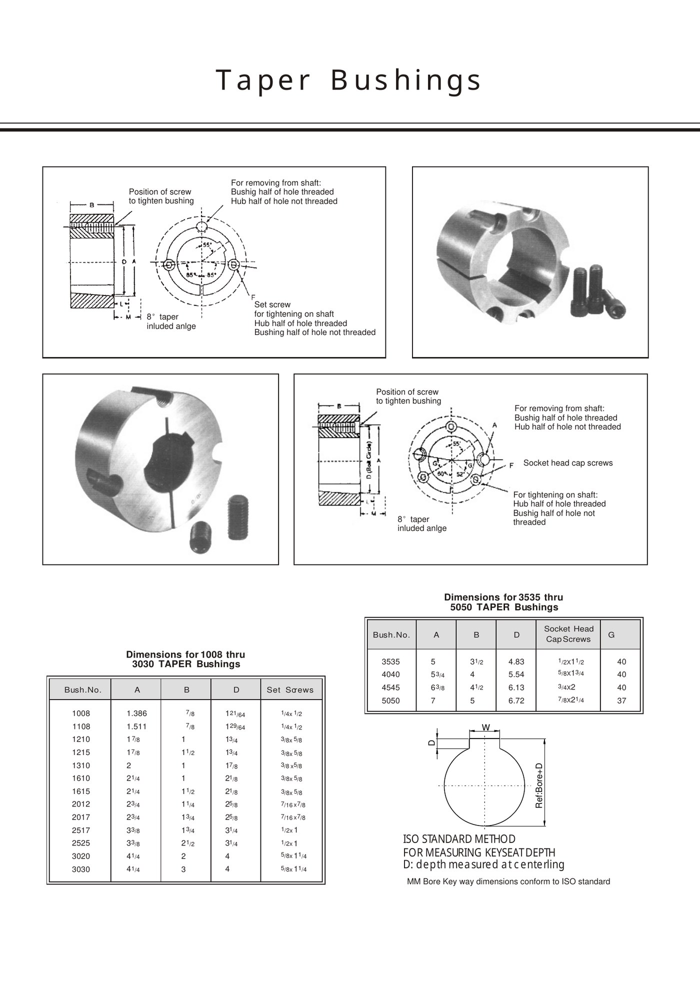
| A / outside or flange reference | Narrows the bushing family. |
| B / axial width | Separates nearby models that share similar outside diameter. |
| D or body diameter | Confirms the matching taper/hub geometry. |
| Fastener size and count | Strong clue to model scale and family. |
| Key width/depth | Confirms the shaft keyway configuration. |
Use dimensional cross-reference, not brand assumption
A replacement claim should be based on measured dimensions and the mating component rather than a brand name alone. If a third-party part number is supplied, use it as an identification clue, then verify the EP candidate against the actual interface. Similar naming conventions do not prove direct interchangeability.
What to check before installing the replacement
Inspect the hub taper, shaft and keyway after the old bushing is removed. Fretting, galling or a worn keyseat may explain why the old part failed. Confirm the new fasteners match the required thread and length, and make sure the installation/removal holes are accessible in the assembled machine.
When a drawing or sample is the fastest route
For an obsolete or modified machine, send the old bushing, a dimensioned sketch or clear photographs with a scale. The goal is to establish the interface rather than to guess an “equivalent.” This is especially important when the installed component has been bored, welded or repaired in the field.
Frequently asked questions
Can I replace a bushing from the shaft bore alone?
No. The outside taper and mating hub family must also match, along with the keyway and fastener arrangement.
What if the original brand and part number are known?
Use them as identification information, then verify dimensions and the mating component before confirming an EP replacement.
Related products and resources
Need help with a real application?
Send the model, shaft diameter, keyway or drawing so the enquiry can be checked against the correct bushing family.
Product Selection
A correct bushing bore starts with a correct shaft measurement. Maintenance records often contain nominal sizes that are useful for purchasing but not enough for diagnosing a worn connection. A shaft stamped “2 in” can have wear, plating, repair material or a tolerance that changes what you actually measure.
The bore also has to belong to the right outside bushing family. Ordering a 50 mm bore in the wrong EP series will not make it fit the existing pulley. Measure the shaft, identify the hub/bushing series and keyway, then state the bore in the original unit.
Stock bore vs custom bore
A stock-bore configuration appears in the product tables for standard purchasing. A custom bore is machined or specified for a requirement outside the listed stock combination or with a special keyway. The RFQ should distinguish the two because the part identification and drawing review can be different.
How to measure the shaft
- Clean a representative length of the shaft before measuring.
- Use an outside micrometer where possible and take readings at more than one angular position.
- Measure near the bushing location, not only at an unworn end of the shaft.
- Record the key width and keyseat condition as well as the diameter.
- Keep inch measurements in inch unless the original design is known to be metric, and vice versa.
Nominal size, tolerance and wear
Nominal shaft size is the design identity; the measured diameter tells you the current condition. If the shaft is materially undersize, tapered, scored or out of round, installing a new bushing may not restore reliable grip. Compare the measurement with the machine drawing or shaft tolerance before treating the bore as a purchasing problem.
Special bore configurations
| Configuration | What to provide |
|---|---|
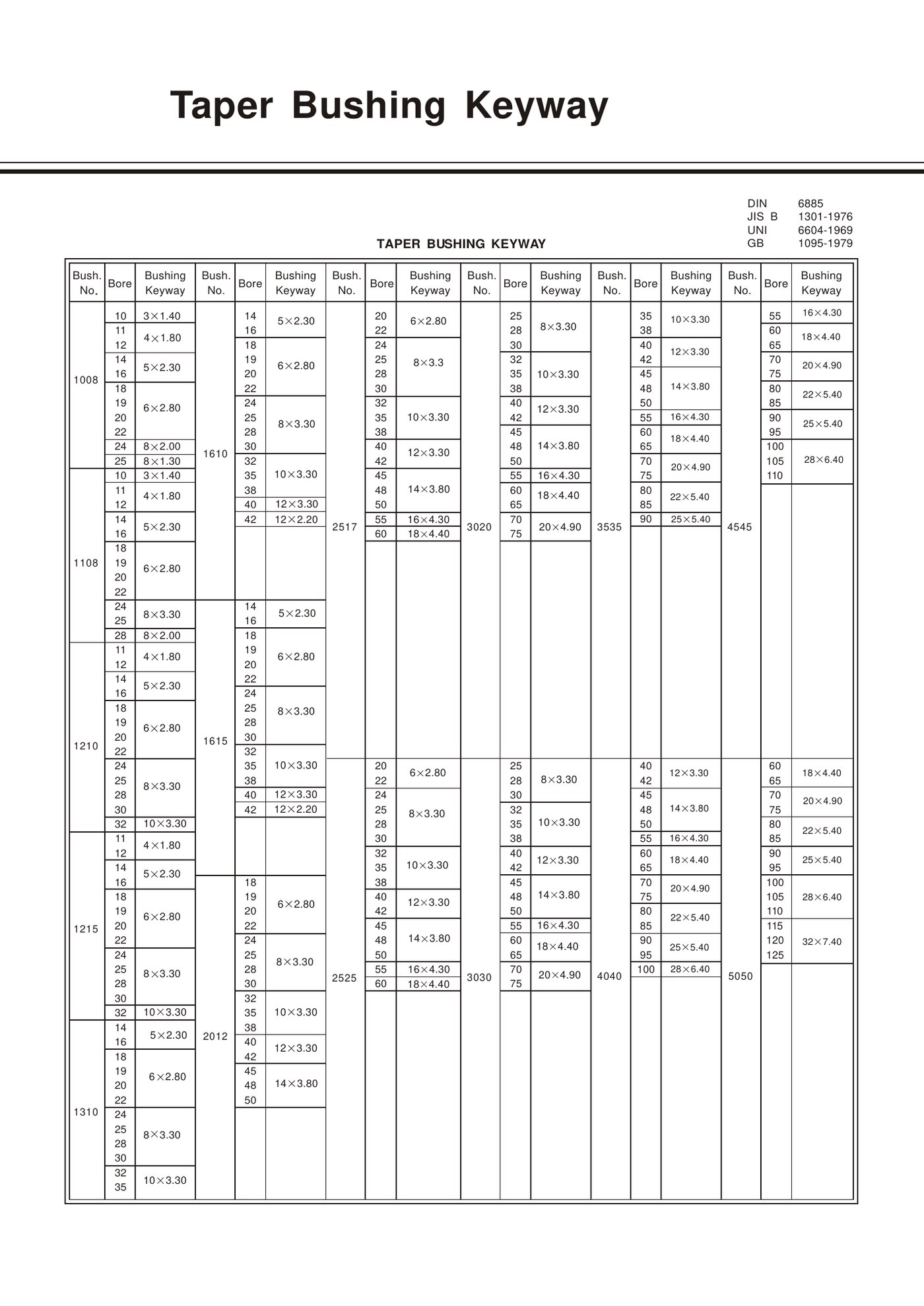
| Metric bore | Exact shaft diameter in mm and the keyway standard. |
| Inch bore | Exact inch size and USAS/ASME or other keyway requirement. |
| No keyway / plain bore | State explicitly that no keyway is required and provide the application drawing. |
| Multiple or special keyways | Provide width, depth, angular position and drawing. |
| Worn-shaft replacement | Provide measured shaft condition; do not simply order an oversized bore without an engineering repair plan. |
How to write the RFQ line
A useful line looks like: “EP-3535 taper bushing, 60 mm bore, DIN 6885 keyway, for existing taper-bore sheave; drawing attached.” If the EP model is unknown, replace it with measured A/B/D dimensions plus photographs of the hub and fastener pattern.
Frequently asked questions
Is a vernier caliper accurate enough for every shaft?
It is useful for identification, but a micrometer is preferred when fit, wear or a close tolerance must be evaluated.
Can I solve a worn shaft by ordering a larger custom bore?
Not automatically. The shaft repair, fit and keyway must be reviewed as a complete mechanical connection.
Related products and resources
Need help with a real application?
Send the model, shaft diameter, keyway or drawing so the enquiry can be checked against the correct bushing family.
Product Selection
Good taper-bushing selection starts with the machine, not the part number alone. Shaft diameter tells you which bores are possible, but the existing hub or new pulley design fixes the outside interface. Duty tells you whether the candidate size is adequate. Keyway and material finish the specification.
The most reliable workflow is sequential: identify the shaft and hub, calculate or obtain the transmitted torque, narrow the EP series, then verify keyway, material and installation access. Skipping the hub check is the fastest way to choose a bushing that fits the shaft but cannot fit the machine.
Step 1: determine the actual shaft diameter
Measure the shaft at several positions with a micrometer when possible. A caliper is useful for a first check, but wear, plating and out-of-round condition can matter on a replacement shaft. Record the unit exactly; do not convert a near-inch measurement into a metric nominal size without checking the machine drawing.
Step 2: determine the transmitted torque
If shaft power and rotational speed are known, the basic engineering relationship for metric units is T = 9550 × P / n, where T is torque in N·m, P is power in kW and n is shaft speed in rpm. The calculated steady torque is only the starting point; start/stop, reversing and shock duty may require an application-specific service factor.
Do not size a bushing from motor nameplate power alone when a gearbox, belt ratio or intermittent peak load changes the torque at the bushing location. Use the torque at the actual shaft connection being designed.
Step 3: match the bore and outside family
| Selection question | What to verify |
|---|---|
| Is this a replacement? | Identify the existing hub/bushing family before changing series. |
| Is this a new component? | Choose the hub or taper-bore pulley together with the bushing family. |
| Does the shaft bore fit? | Confirm the required inch or metric bore is available or can be specified. |
| Is the duty adequate? | Check model-specific torque/capacity data for the complete assembly. |
| Can it be installed and removed? | Leave access for the tightening and jack-screw positions. |
Step 4: specify the keyway standard
For keyed shafts, state the applicable USAS/ASME, DIN 6885, JIS B 1301 or BS convention, or provide the actual measured key dimensions. Country of installation is not enough to determine the standard on imported machinery.
Step 5: choose material and environment
Use the material specified for the product family unless the environment calls for a reviewed alternative. Shock, corrosion, washdown and temperature can change the discussion, but material does not compensate for wrong fit, misalignment or an undersized connection. For special steel or stainless requests, include the environment and drawing.
Step 6: verify the hub and assembly
Confirm the mating hub bore, axial width, screw access, pulley/sprocket alignment and surrounding machine clearance. Before ordering a replacement, inspect the hub taper for wear or fretting; a new bushing cannot restore a damaged mating surface.
Frequently asked questions
Can shaft diameter alone identify the right bushing?
No. The mating hub family, duty, keyway and available installation geometry must also match.
Should I include a service factor in the torque check?
Use the service factor required by the machine or drive-design method for shock, reversing or other non-steady duty.
Related products and resources
Selection Engineering Guide
Use the selection workflow and model tables to confirm the required series.
Need help with a real application?
Send the model, shaft diameter, keyway or drawing so the enquiry can be checked against the correct bushing family.