Technical Knowledge
Complete Taper Lock Bushing Size Chart: EP-1008 to EP-5050 Dimensions Reference
Technical Knowledge
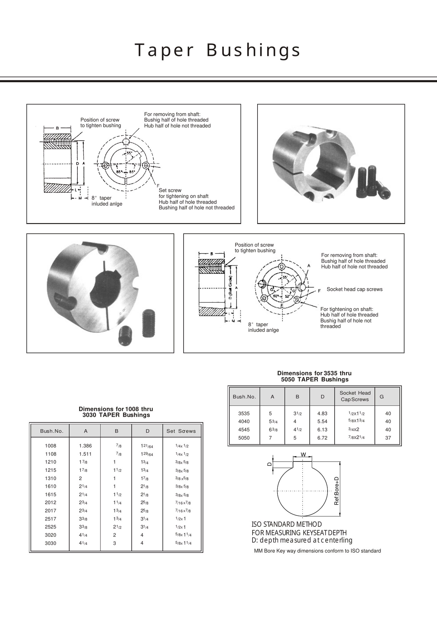
A size chart is most useful when it helps identify a real part, not when it is treated as a substitute for the full drawing. For EP taper-lock bushings, the A, B and D dimensions narrow the series, while the shaft bore, keyway and fastener arrangement complete the identification.
Several neighbouring models share the same A and D values but use a different B width. That is why an EP-2012 and EP-2017 can look nearly identical in a photograph yet still require different axial space and model identification.
How to read the EP model and dimensional table
Use the stamped model when it is readable. If the marking has worn away, measure A, B and D at undamaged surfaces, record the fastener size and then check the shaft bore/keyway. Do not infer bore from the model suffix alone; stock and custom bore configurations need to be verified separately.
EP-1008 to EP-5050 dimensions
| EP model | A (in) | B (in) | D (in) | Listed fastener |
|---|---|---|---|---|
| EP-1008 | 1.386 | 7/8 | 1 21/64 | 1/4 x 1/2 set screws |
| EP-1108 | 1.511 | 7/8 | 1 29/64 | 1/4 x 1/2 set screws |
| EP-1210 | 1 7/8 | 1 | 1 3/4 | 3/8 x 5/8 set screws |
| EP-1215 | 1 7/8 | 1 1/2 | 1 3/4 | 3/8 x 5/8 set screws |
| EP-1310 | 2 | 1 | 1 7/8 | 3/8 x 5/8 set screws |
| EP-1610 | 2 1/4 | 1 | 2 1/8 | 3/8 x 5/8 set screws |
| EP-1615 | 2 1/4 | 1 1/2 | 2 1/8 | 3/8 x 5/8 set screws |
| EP-2012 | 2 3/4 | 1 1/4 | 2 5/8 | 7/16 x 7/8 set screws |
| EP-2017 | 2 3/4 | 1 3/4 | 2 5/8 | 7/16 x 7/8 set screws |
| EP-2517 | 3 3/8 | 1 3/4 | 3 1/4 | 1/2 x 1 set screws |
| EP-2525 | 3 3/8 | 2 1/2 | 3 1/4 | 1/2 x 1 set screws |
| EP-3020 | 4 1/4 | 2 | 4 | 5/8 x 1 1/4 set screws |
| EP-3030 | 4 1/4 | 3 | 4 | 5/8 x 1 1/4 set screws |
| EP-3535 | 5 | 3 1/2 | 4.83 | 1/2 x 1 1/2 socket head cap screws |
| EP-4040 | 5 3/4 | 4 | 5.54 | 5/8 x 1 3/4 socket head cap screws |
| EP-4545 | 6 3/8 | 4 1/2 | 6.13 | 3/4 x 2 socket head cap screws |
| EP-5050 | 7 | 5 | 6.72 | 7/8 x 2 1/4 socket head cap screws |
Large series beyond EP-5050
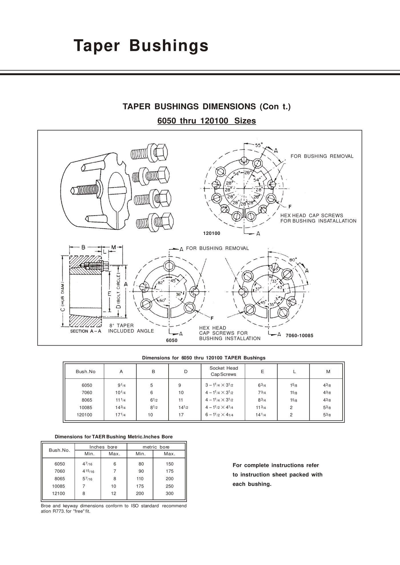
| EP model | A (in) | B (in) | D (in) | Listed bore range |
|---|---|---|---|---|
| EP-6050 | 9 1/4 | 5 | 9 | 4 7/16 to 6 in |
| EP-7060 | 10 1/4 | 6 | 10 | 4 15/16 to 7 in |
| EP-8065 | 11 1/4 | 6 1/2 | 11 | 5 7/16 to 8 in |
| EP-10085 | 14 3/4 | 8 1/2 | 14 1/2 | 7 to 10 in |
| EP-120100 | 17 1/4 | 10 | 17 | 8 to 12 in |
How to select the correct series for a shaft
Start with the actual shaft diameter and the mating component. The bushing outside taper must match the hub, and the required shaft bore must be available or specified for that series. If you are designing a new hub, the model can be selected around shaft size and duty; if you are replacing a part, the existing hub usually fixes the family first.
For a worn or unknown bushing, send the measured A/B/D dimensions, shaft diameter, keyway, screw size and photographs. That information is more reliable than trying to identify the part from outside diameter alone.
Use the drawing with the table
The table gives quick dimensions, but the technical drawing shows which surfaces the letters refer to and where tightening/removal holes are located. On larger series, also check screw quantity and handling space around the hub.
Frequently asked questions
Can I identify a bushing from A and D dimensions only?
Sometimes those dimensions narrow the family, but B width, fasteners, shaft bore, keyway and the mating hub should also be checked.
Does the model number guarantee one bore size?
No. Confirm the ordered or existing bore and keyway configuration for the exact bushing.
Related products and resources
Need help with a real application?
Send the model, shaft diameter, keyway or drawing so the enquiry can be checked against the correct bushing family.