taper-bush
Product Deep-Dive
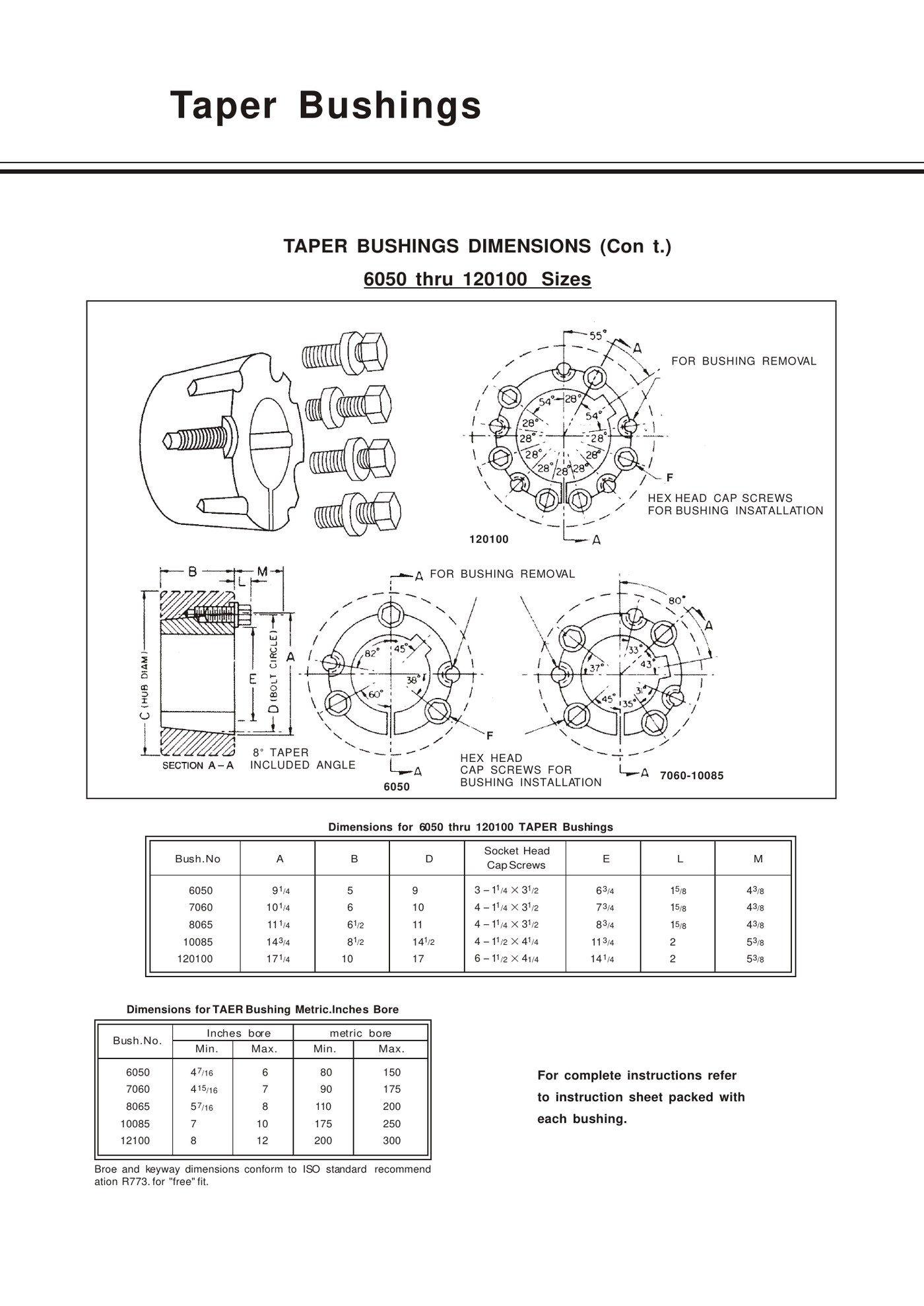
When a shaft and hub outgrow the EP-5050 family, large taper-lock bushings become a different maintenance task as well as a larger part. The EP-6050 through EP-120100 range increases outside dimensions, bore range, fastener count and component weight, so lifting, access and surface inspection have to be planned before installation.
These models are used wherever the machine requires their geometry and capacity—large conveyors, crushers, mills or other heavy drives are typical contexts. Application name alone does not select the model; the shaft, hub and transmitted duty still control the decision.
EP-6050 to EP-120100 dimension and bore reference
| EP model | A (in) | B (in) | D (in) | Fastener reference | Listed bore range |
|---|---|---|---|---|---|
| EP-6050 | 9 1/4 | 5 | 9 | 3 × 1 1/4 × 3 1/2 socket-head cap screws | 4 7/16 to 6 in |
| EP-7060 | 10 1/4 | 6 | 10 | 4 × 1 1/4 × 3 1/2 socket-head cap screws | 4 15/16 to 7 in |
| EP-8065 | 11 1/4 | 6 1/2 | 11 | 4 × 1 1/4 × 3 1/2 socket-head cap screws | 5 7/16 to 8 in |
| EP-10085 | 14 3/4 | 8 1/2 | 14 1/2 | 4 × 1 1/2 × 4 1/4 socket-head cap screws | 7 to 10 in |
| EP-120100 | 17 1/4 | 10 | 17 | 6 × 1 1/2 × 4 1/4 socket-head cap screws | 8 to 12 in |
What changes compared with smaller taper-lock series
The large models use multiple large socket-head cap screws, and the number increases on EP-120100. Their bore ranges reach much larger shafts, and the surrounding hub must provide enough material and service clearance. Installation is not a one-person bench task at the upper end of the range; the machine maintenance plan should cover lifting and safe support.
Surface preparation and contact inspection
Clean the shaft and mating taper carefully and inspect for corrosion, scoring or old fretting. On a large bushing, forcing a damaged taper together creates high local stress and makes later removal difficult. Verify the mating hub model and the bushing A/B/D dimensions before committing to installation.
Keyway and metric-bore considerations
Large-series data includes both inch and metric bore references. State units explicitly and specify the keyway standard or measured key dimensions. When an imported machine has a metric shaft but an inch-series hub, treat the bore and outside bushing identity as separate pieces of information.
Heavy-industry RFQ checklist
Provide the EP or existing model, shaft bore, keyway, hub or pulley reference, drive torque or power/speed at the bushing shaft, duty description, environment, lifting/access limitations and quantity. For a replacement after failure, include photos of the shaft, key and taper condition.
Frequently asked questions
Can EP-6050 through EP-120100 be selected only from shaft diameter?
No. Shaft bore narrows the range, but the mating hub, torque/duty, keyway and installation geometry must also be verified.
Do large bushings need special handling?
At the upper sizes, plan safe lifting and support for the bushing and driven component according to the machine maintenance procedure.
Related products and resources
Need help with a real application?
Send the model, shaft diameter, keyway or drawing so the enquiry can be checked against the correct bushing family.
Product Deep-Dive
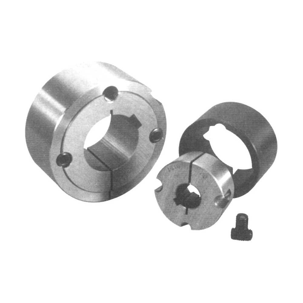
A taper bore adapter is useful when a component has a straight bore but the machine standard calls for a removable taper-bushing shaft connection. The adapter creates the tapered interface that the component does not have on its own, allowing the selected bushing to be used without replacing the entire driven component.
The conversion is only safe when the component has enough material and the adapter dimensions are matched correctly. An adapter cannot compensate for a thin, cracked or poorly aligned hub, and it should not be selected from shaft diameter alone.
How the adapter changes the interface
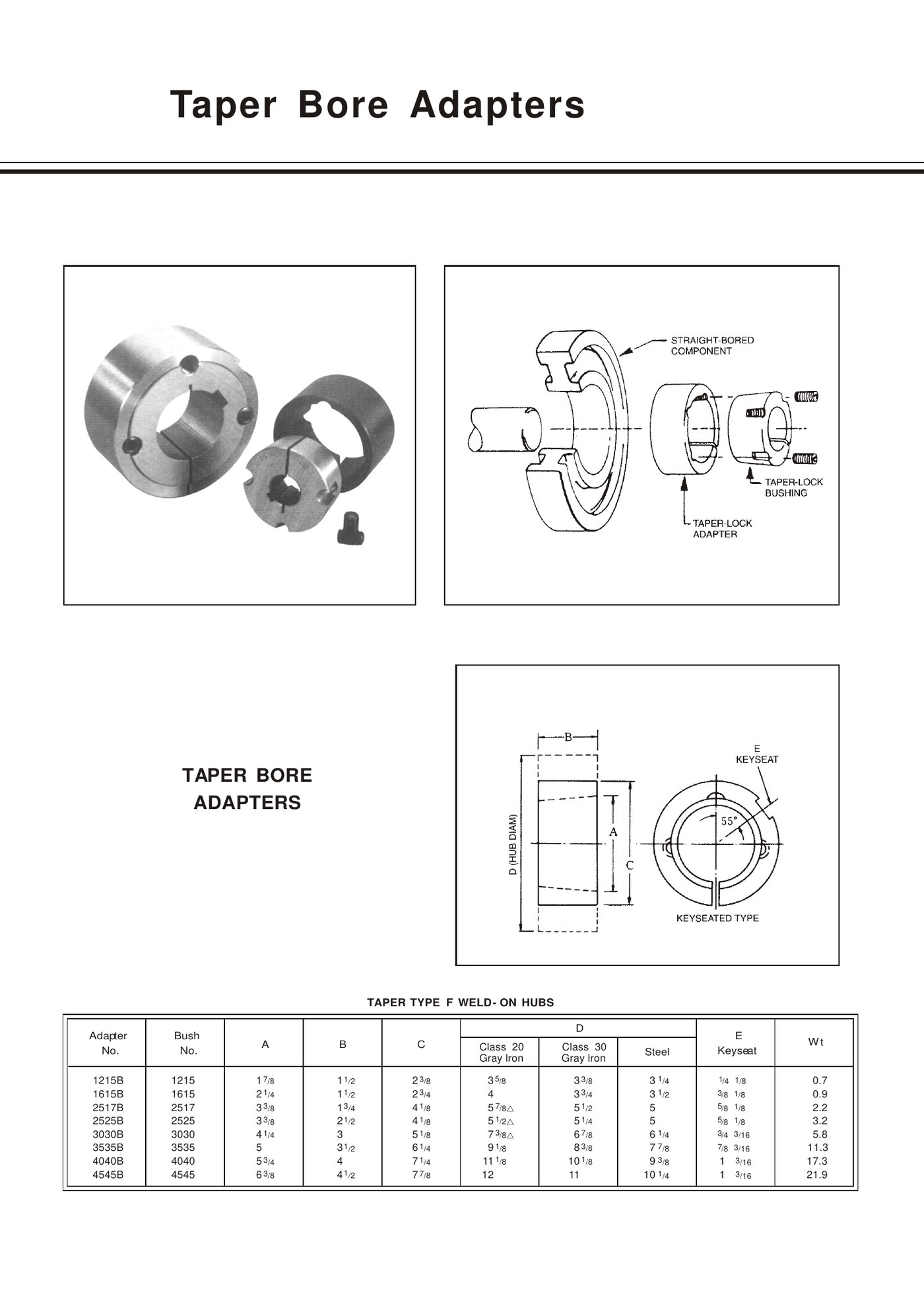
The adapter sits between the straight-bore component and the taper bushing. Its geometry must match the selected bushing series on one side and the component bore on the other. The table links each EP adapter to the bushing number it is designed around.
EP-1215B to EP-4545B reference
| EP adapter | Matched EP bushing | A (in) | B (in) | C (in) | Approx. weight (lb) |
|---|---|---|---|---|---|
| EP-1215B | EP-1215 | 1 7/8 | 1 1/2 | 2 3/8 | 0.7 |
| EP-1615B | EP-1615 | 2 1/4 | 1 1/2 | 2 3/4 | 0.9 |
| EP-2517B | EP-2517 | 3 3/8 | 1 3/4 | 4 1/8 | 2.2 |
| EP-2525B | EP-2525 | 3 3/8 | 2 1/2 | 4 1/8 | 3.2 |
| EP-3030B | EP-3030 | 4 1/4 | 3 | 5 1/8 | 5.8 |
| EP-3535B | EP-3535 | 5 | 3 1/2 | 6 1/4 | 11.3 |
| EP-4040B | EP-4040 | 5 3/4 | 4 | 7 1/4 | 17.3 |
| EP-4545B | EP-4545 | 6 3/8 | 4 1/2 | 7 7/8 | 21.9 |
Material and keyseat dimensions
The adapter table provides outside-diameter references for Class 20 gray iron, Class 30 gray iron and steel, plus a keyseat dimension. Those choices affect the component being adapted and the available wall section. Specify the component material and intended adapter material when a conversion is not already defined by a drawing.
Typical retrofit situations
Adapters can be used when a straight-bore sprocket, pulley or fabricated hub needs to join a taper-bushing system without machining a new taper directly in the component. They are especially useful in field retrofits where the driven part is still serviceable but the shaft connection needs to become removable or standardized.
Installation and engineering checks
Verify the straight-bore component is concentric and has enough material for the adapter outside diameter. Check the adapter keyseat, bushing model, shaft bore and axial length, then inspect final runout/alignment after assembly. A conversion should be reviewed as a new hub assembly, not simply as an added sleeve.
Frequently asked questions
Can an adapter convert any straight-bore pulley to Taper Lock?
No. The component must have suitable bore size, wall section, material and geometry for the selected adapter and load.
How do I choose between EP-2517B and EP-2525B?
They match different bushing widths even though some outside dimensions are similar. Use the matched bushing number and the full A/B/C dimensions.
Related products and resources
Need help with a real application?
Send the model, shaft diameter, keyway or drawing so the enquiry can be checked against the correct bushing family.
Product Deep-Dive
A QD weld-on hub is a fabrication component that brings a standard QD bushing interface into a plate, sprocket, sheave or other suitable steel assembly. The hub is welded to the fabricated component; the removable QD bushing is then installed in the finished taper-bored hub to mount the assembly on the shaft.
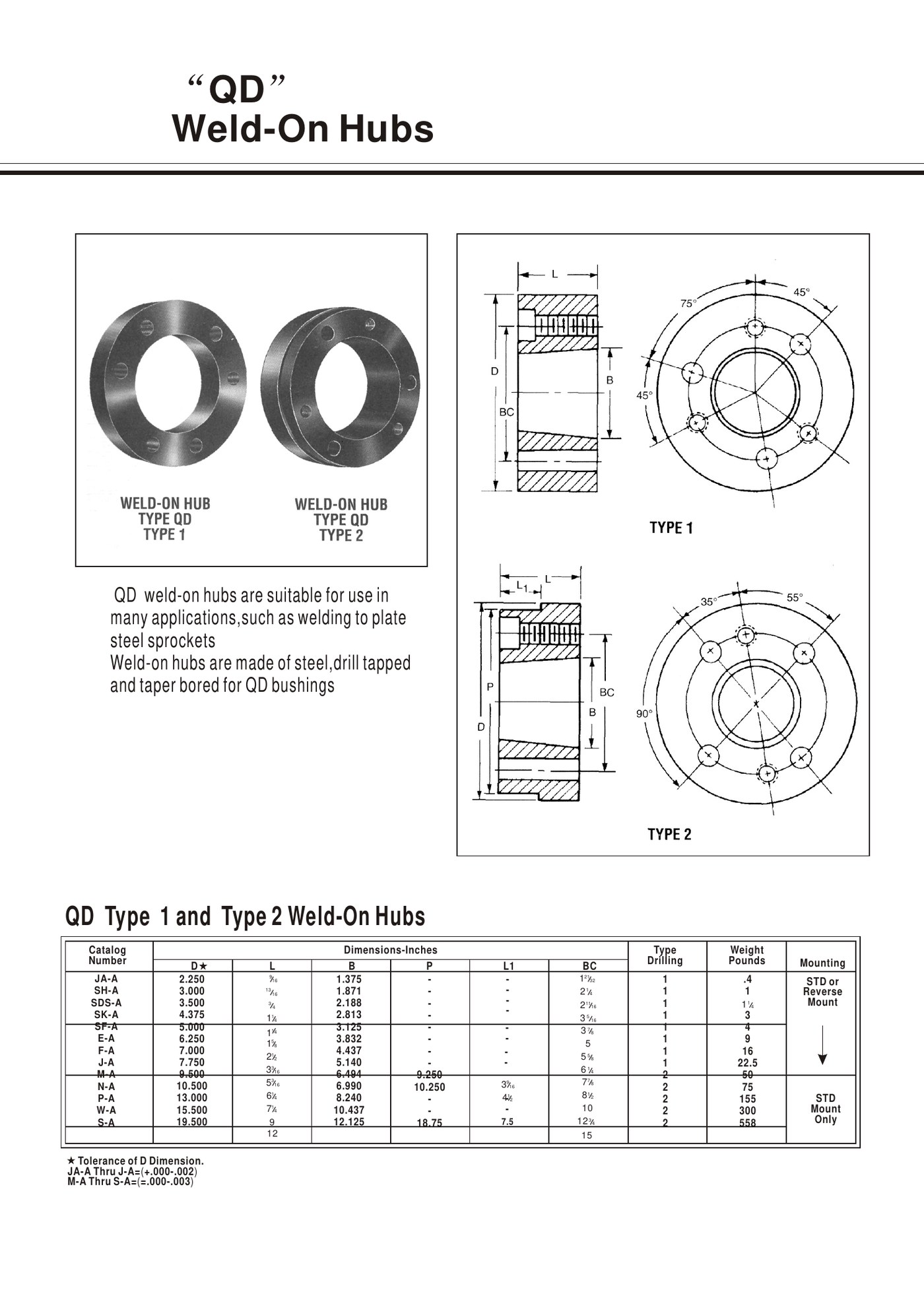
The EP technical data identifies QD Type 1 and Type 2 weld-on hub families from EP-JA-A through EP-S-A and states that the hubs are steel, drill-tapped and taper-bored for QD bushings. Type selection is part of the geometry, not a cosmetic choice.
How a QD weld-on hub works
The weld-on hub provides the outside fabrication surface and the internal QD taper. Once it is welded into the component, the selected QD bushing supplies the shaft bore and keyway. This modular arrangement lets a fabricated sprocket or plate share a standardized removable shaft interface.
Type 1 and Type 2 are different fabrication references
The catalogue groups weld-on hubs by Type 1 and Type 2 drilling/mounting arrangements. Before cutting the plate or preparing the weld joint, identify the exact hub type and QD size. Hole positions, outside diameter and mounting orientation should be taken from the correct drawing.
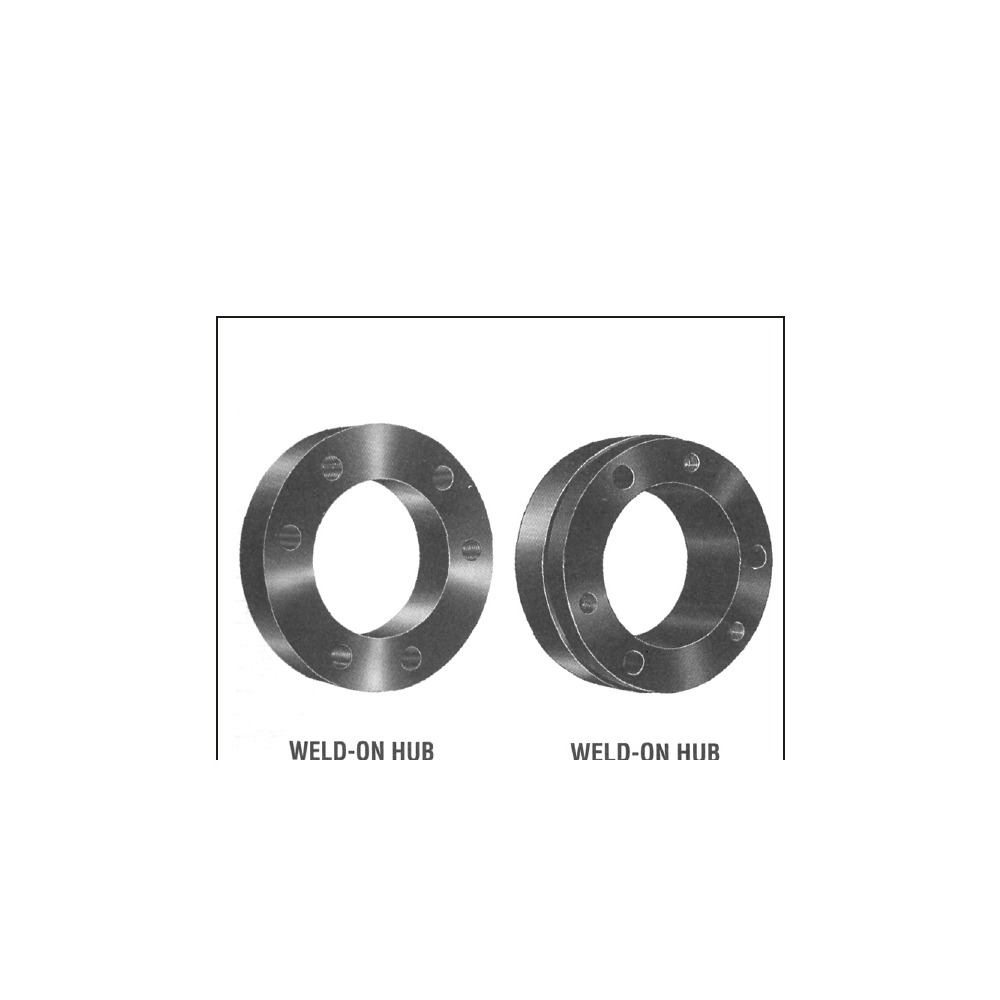
EP QD weld-on hub family
| EP hub reference | Matched QD family check | Fabrication note |
|---|---|---|
| EP-JA-A / EP-SH-A / EP-SDS-A / EP-SK-A | Confirm the matching smaller QD bushing family. | Use the exact D/L/B and bolt-circle drawing for the chosen hub. |
| EP-SF-A / EP-E-A / EP-F-A / EP-J-A | Confirm EP-SF/E/F/J QD interface. | Verify plate thickness, weld access and final alignment. |
| EP-M-A / EP-N-A / EP-P-A | Confirm EP-M/N/P QD interface. | Heavier hubs require controlled handling and distortion checks. |
| EP-W-A / EP-S-A | Confirm large QD interface. | Review component structure, weld procedure and final machining/alignment needs. |
Typical applications
Common uses include welding a QD hub into a plate sprocket for conveyor chain service, creating a fabricated belt sheave or fan hub, or adapting a custom steel plate to a standard QD shaft connection. The hub does not determine the application rating by itself; the welded assembly must be designed for the actual load.
Welding and post-weld checks
Use a welding procedure appropriate to the hub and parent component, controlling heat input and distortion. Do not weld with the removable QD bushing installed. After cooling, verify the hub has not pulled out of alignment and that the taper, threads and bolt pattern remain clean and undamaged before fitting the bushing.
Frequently asked questions
Can the QD bushing itself be welded to the plate?
No. The weld-on hub is the fabricated steel component; the QD bushing remains a removable shaft interface.
Are Type 1 and Type 2 interchangeable?
Do not assume so. Confirm the exact drawing, drilling/mounting arrangement and matched QD size before fabrication.
Related products and resources
Need help with a real application?
Send the model, shaft diameter, keyway or drawing so the enquiry can be checked against the correct bushing family.