Product Selection
How to Select the Right Taper Lock Bushing: A Practical Engineering Guide
Product Selection
Good taper-bushing selection starts with the machine, not the part number alone. Shaft diameter tells you which bores are possible, but the existing hub or new pulley design fixes the outside interface. Duty tells you whether the candidate size is adequate. Keyway and material finish the specification.
The most reliable workflow is sequential: identify the shaft and hub, calculate or obtain the transmitted torque, narrow the EP series, then verify keyway, material and installation access. Skipping the hub check is the fastest way to choose a bushing that fits the shaft but cannot fit the machine.
Step 1: determine the actual shaft diameter
Measure the shaft at several positions with a micrometer when possible. A caliper is useful for a first check, but wear, plating and out-of-round condition can matter on a replacement shaft. Record the unit exactly; do not convert a near-inch measurement into a metric nominal size without checking the machine drawing.
Step 2: determine the transmitted torque
If shaft power and rotational speed are known, the basic engineering relationship for metric units is T = 9550 × P / n, where T is torque in N·m, P is power in kW and n is shaft speed in rpm. The calculated steady torque is only the starting point; start/stop, reversing and shock duty may require an application-specific service factor.
Do not size a bushing from motor nameplate power alone when a gearbox, belt ratio or intermittent peak load changes the torque at the bushing location. Use the torque at the actual shaft connection being designed.
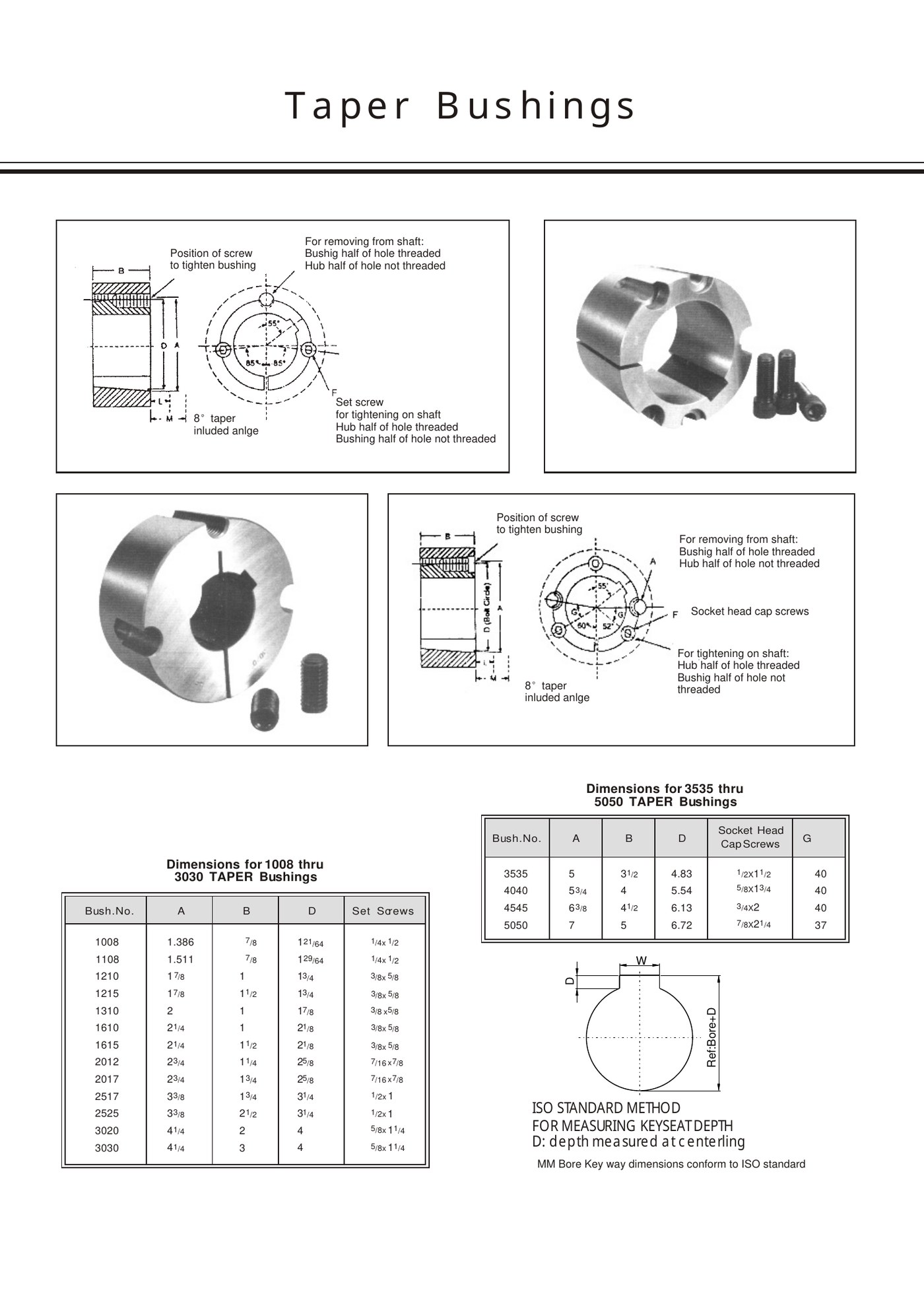
Step 3: match the bore and outside family
| Selection question | What to verify |
|---|---|
| Is this a replacement? | Identify the existing hub/bushing family before changing series. |
| Is this a new component? | Choose the hub or taper-bore pulley together with the bushing family. |
| Does the shaft bore fit? | Confirm the required inch or metric bore is available or can be specified. |
| Is the duty adequate? | Check model-specific torque/capacity data for the complete assembly. |
| Can it be installed and removed? | Leave access for the tightening and jack-screw positions. |
Step 4: specify the keyway standard
For keyed shafts, state the applicable USAS/ASME, DIN 6885, JIS B 1301 or BS convention, or provide the actual measured key dimensions. Country of installation is not enough to determine the standard on imported machinery.
Step 5: choose material and environment
Use the material specified for the product family unless the environment calls for a reviewed alternative. Shock, corrosion, washdown and temperature can change the discussion, but material does not compensate for wrong fit, misalignment or an undersized connection. For special steel or stainless requests, include the environment and drawing.
Step 6: verify the hub and assembly
Confirm the mating hub bore, axial width, screw access, pulley/sprocket alignment and surrounding machine clearance. Before ordering a replacement, inspect the hub taper for wear or fretting; a new bushing cannot restore a damaged mating surface.
Frequently asked questions
Can shaft diameter alone identify the right bushing?
No. The mating hub family, duty, keyway and available installation geometry must also match.
Should I include a service factor in the torque check?
Use the service factor required by the machine or drive-design method for shock, reversing or other non-steady duty.
Related products and resources
Selection Engineering Guide
Use the selection workflow and model tables to confirm the required series.
Need help with a real application?
Send the model, shaft diameter, keyway or drawing so the enquiry can be checked against the correct bushing family.