taper-bush
Product Comparison
Material names matter because they describe how a bushing may respond to machining, clamping and shock, but they should not be treated as a shortcut for application design. A cast-iron bushing in a correctly selected, steady drive can be entirely appropriate; a high-impact or corrosive duty may justify another material only after the complete connection is reviewed.
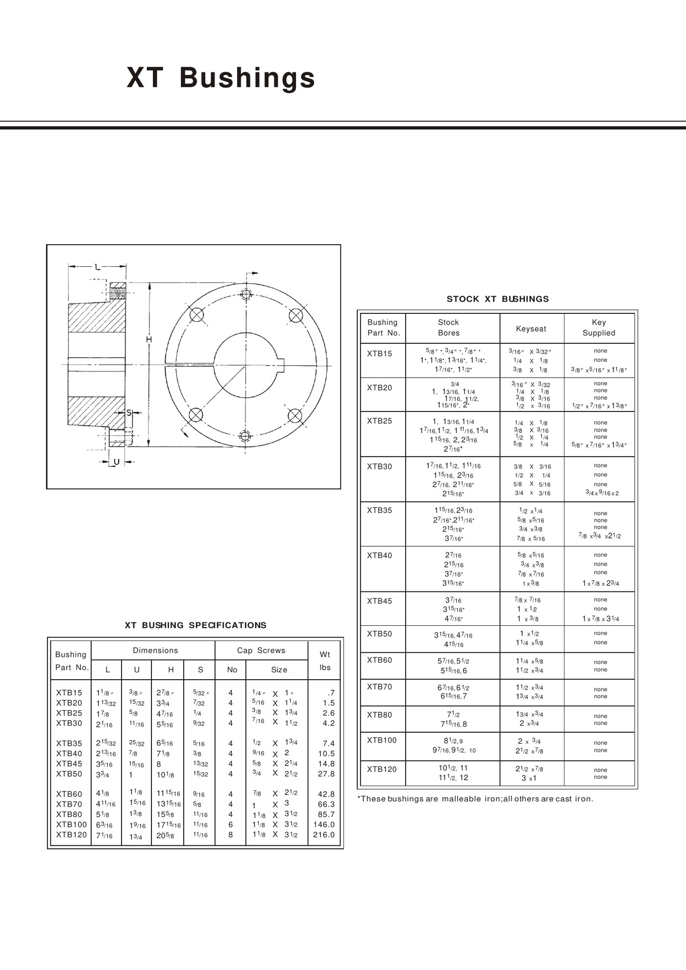
The XT stock-bore table is especially useful because it marks selected bore entries with an asterisk and states that those marked bushings are malleable iron while the other entries are cast iron. The mark applies to the listed stock-bore entries, not automatically to every bushing in a model family.
Cast iron in taper bushing service
Gray cast iron is common in industrial hubs and bushings because it machines well, is dimensionally stable and suits many steady mechanical loads. Its limitation is lower ductility than steel or malleable iron, so impact, abuse during installation and severe stress concentration deserve attention. The material choice should be paired with correct shaft fit and hub geometry.
Malleable iron and the XT asterisk notation
Malleable iron is produced through heat treatment that changes the microstructure and gives greater ductility than ordinary gray cast iron. In the XT stock-bore table, an asterisk identifies the entries specified as malleable iron. If material is important to a replacement, quote the exact EP-XTB model and stock bore rather than asking for “malleable XT” generically.
Material comparison for selection
| Decision factor | Cast iron | Malleable iron |
|---|---|---|
| Typical role | General industrial bushing/hub construction where the catalogue specifies it. | Selected stock-bore XT entries where the catalogue marks malleable iron. |
| Ductility | Lower; avoid impact damage and stress concentration. | Higher than gray cast iron, useful where additional toughness is specified. |
| Machining/fit | Good machinability; final fit still depends on bore/keyway tolerances. | Machinable, but replacement must match the specified material and dimensions. |
| Selection rule | Use when the exact model/configuration calls for cast iron. | Use when the exact model/bore is marked or a custom specification requires it. |
Shock, corrosion and special materials
Do not infer that malleable iron alone makes a connection suitable for mining, agriculture or reversing shock. Shaft condition, keyway, hub thickness, fasteners and duty all matter. For corrosion or hygiene-sensitive service, the relevant discussion may shift to steel, stainless steel, coating or a custom component rather than simply switching iron grade.
How to specify material in an RFQ
State the product family, model, bore and keyway first, then add the required material or environment. If you are replacing an existing bushing, include a photo of the marking and any material documentation available from the machine. For custom stainless or steel requests, a drawing is preferable to a material name alone.
Frequently asked questions
Are all EP-XTB15 to EP-XTB35 bushings malleable iron?
No. The XT stock-bore table marks selected entries with an asterisk; those marked entries are identified as malleable iron, while the other entries are cast iron.
Should I automatically choose malleable iron for shock loads?
Treat material as one part of the duty review. Confirm the exact bushing configuration, shaft/hub condition and load before changing material.
Related products and resources
Need help with a real application?
Send the model, shaft diameter, keyway or drawing so the enquiry can be checked against the correct bushing family.
Product Comparison
XT and QD bushings are both flanged, removable shaft connections, so they can look related in photographs. Their model systems and mating hubs are different, however, and that difference controls replacement. An EP-XTB50 belongs with a matching XT hub arrangement; an EP-J-STL belongs with a QD-style component.
For engineers and MRO teams, the useful question is not which family is “better” in isolation. It is which interface matches the machine, which bore/keyway is required, and which hub geometry can be verified from a drawing or measured part.
What is an XT bushing?
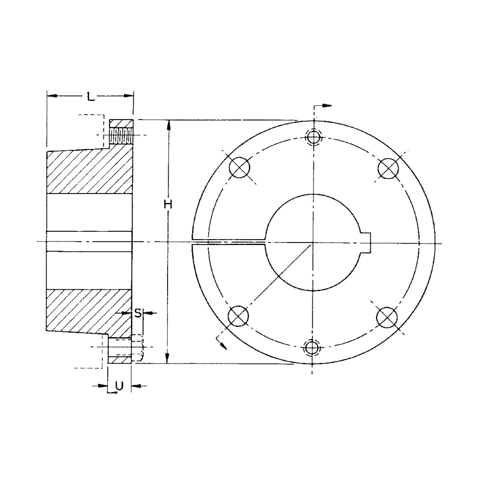
The EP XT family runs from EP-XTB15 to EP-XTB120. The catalogue gives L, U, H and S dimensions, cap-screw quantity/size, stock bore information and matching XT hub references. The largest XT models use more fasteners and substantially heavier components, so handling and access become part of the maintenance plan.
What is a QD bushing?
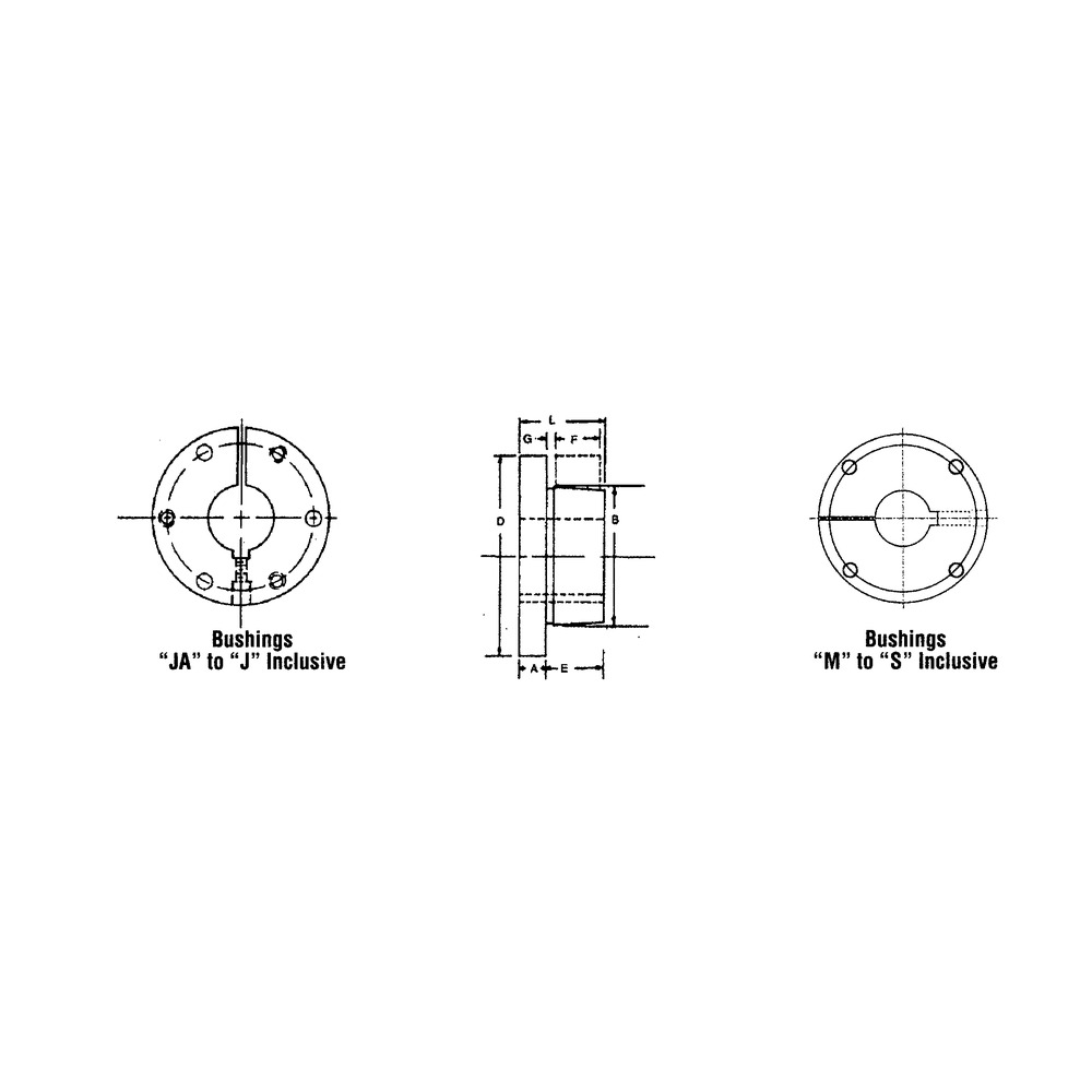
The EP QD steel group uses lettered sizes such as SF, E, F, J, M and N, with a distinct flange/barrel shape and standard or shallow keyway options. QD weld-on hubs extend the interface into fabricated sprockets and plates. Selection begins with the QD size and mating component, then moves to bore and keyway.
Head-to-head comparison
| Check | XT | QD |
|---|---|---|
| Model system | EP-XTB15 through EP-XTB120. | Lettered EP QD series such as SF, E, F, J, M, N. |
| Mating hub | Matching XT hub reference and type. | Matching QD sheave, sprocket or QD weld-on hub. |
| Key technical dimensions | L, U, H, S, bore/keyseat and cap screws. | A/B/D or QD geometry, bore/keyway and flange/bolt pattern. |
| Replacement approach | Measure hub/bushing and verify XTB/XTH identity. | Verify QD size and mating component before bore selection. |
| Direct substitution | Not with a QD hub. | Not with an XT hub. |
When XT is the established machine interface
Use XT when the existing sheave, pulley or fabricated hub is clearly an XT system, or when a new design is being built around an XT hub family. On old equipment, the H dimension, screw count, bore and hub marking are strong identification clues when the stamped XTB code is worn.
When QD is the established machine interface
Use QD where the existing component has the QD flange/barrel pattern, or where a QD weld-on hub is intentionally being fabricated into the driven component. Do not infer QD size only from the shaft bore; several families can overlap in bore while using different outside geometry.
Frequently asked questions
Can an XT bushing be installed in a QD hub?
No. XT and QD are different interface families and the mating hub must match the bushing system.
What should I measure if the part number is unreadable?
Record the shaft bore, flange/body dimensions, cap-screw size/count, keyway and the mating hub dimensions, then compare those measurements with the correct family drawing.
Related products and resources
Need help with a real application?
Send the model, shaft diameter, keyway or drawing so the enquiry can be checked against the correct bushing family.
Product Comparison
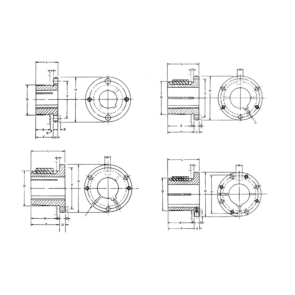
“Split” and “solid” are often used loosely in maintenance conversations, but the practical issue is the complete shaft-to-hub system. A split taper bushing is designed around a specific split body and matching hub geometry; a one-piece taper-lock or straight hub arrangement uses a different interface.
The right comparison is therefore not simply strength versus convenience. Look at how the component locates concentrically, how the fasteners are accessed, what has to be removed during service, and whether the existing hub can accept the proposed bushing family.
Split Taper design and advantages
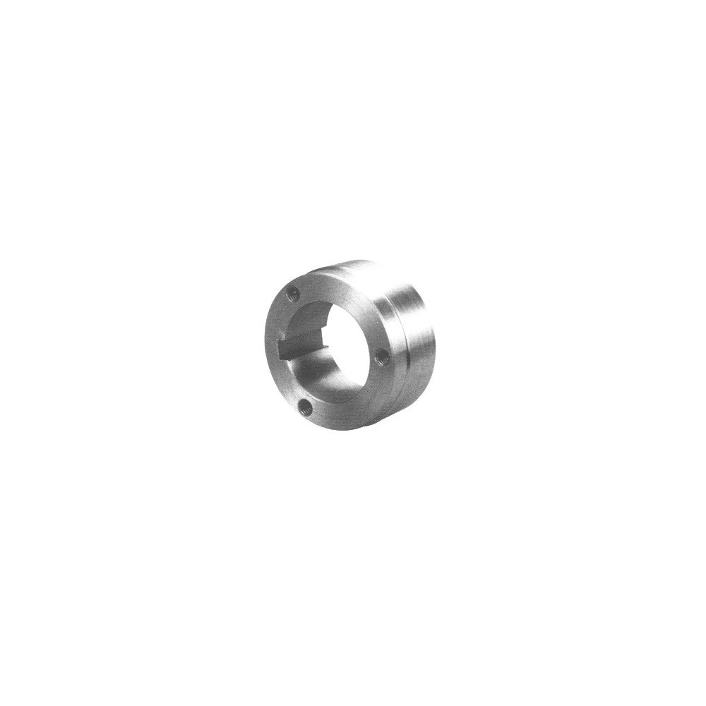
The EP Split Taper family includes Type 1 and Type 2 configurations and matching steel hubs. The split geometry lets the bushing clamp as the assembly is drawn into its mating hub. Accurate identification of the type, family letter, bore and hub dimensions is important because a visually similar split bushing can still have the wrong flange or hub interface.
One-piece taper-style connections
A one-piece taper-lock bushing uses its own tapered outside interface and tightening/removal pattern. It is compact and widely used with dedicated taper-bore pulleys, sprockets and hubs. If the machine was built around this family, changing to Split Taper is not a bushing-only substitution; the mating component must change too.
Comparison for engineering decisions
| Criterion | Split Taper | One-piece Taper Lock style |
|---|---|---|
| Mating component | Matching Split Taper hub, Type 1/Type 2 as applicable. | Matching taper-lock hub or taper-bore component. |
| Identification | Family/type, bore, keyway and hub dimensions. | Numbered series, A/B/D geometry, bore/keyway and fasteners. |
| Service access | Depends on flange and bolt access around the hub. | Depends on tightening and removal-hole access. |
| Alignment control | Check concentricity and final drive alignment after assembly. | Check taper seating and final drive alignment after assembly. |
| Direct interchange | Only with matching Split Taper geometry. | Only with matching taper-lock geometry. |
Where Split Taper is often considered
Split Taper can be attractive where the machine already uses matching split-taper hubs, especially in pulley, sheave and rotating-drive assemblies where service teams value clear hub/bushing identification. The catalogue includes several family letters and separate Type 1/Type 2 references, so selection should be drawing-led rather than based on diameter alone.
Where Taper Lock is often considered
Taper Lock fits naturally when the component is already available with a taper-lock bore, when a compact numbered series is preferred, or when existing plant spares are standardized around that family. The decision should still include shaft fit, keyway, fastener access, duty and the condition of the mating hub.
Frequently asked questions
Is a Split Taper bushing automatically more accurate at high speed?
Do not assume a performance advantage from the split alone. Final concentricity depends on the complete hub, shaft, machining and assembly condition.
Can I replace a Taper Lock bushing with Split Taper without changing the pulley?
Normally no. The mating hub geometry is different, so the driven component must be designed for the selected family.
Related products and resources
Need help with a real application?
Send the model, shaft diameter, keyway or drawing so the enquiry can be checked against the correct bushing family.
Product Comparison
Taper Lock and QD bushings solve the same broad problem—mounting a rotating component on a shaft—but they are not two names for one interface. The mating hub geometry, flange arrangement and fastener positions differ, so the machine usually tells you which family belongs there.
For a new design, the choice can be made around available hub products, space and service requirements. For replacement work, start with the existing sheave, sprocket or hub and identify its interface before comparing bore ranges or price.
What is a Taper Lock bushing?
The EP Taper Lock range uses a compact tapered interface with tightening and removal-hole positions that vary across the model range. Smaller models use set-screw arrangements, while larger models move to socket-head cap screws. The bushing and mating component must be selected as a matched taper system.
What is a QD bushing?
QD bushings use a split flange/barrel arrangement and dedicated QD mating components. The EP QD range includes lettered sizes and standard or shallow keyway references. QD weld-on hubs can also be incorporated into fabricated sprockets or plates when the QD size and drilling arrangement are chosen before fabrication.
Side-by-side comparison
| Decision point | Taper Lock | QD |
|---|---|---|
| Mating interface | Compact taper-lock hub bore matched to the EP series. | QD flange/barrel interface matched to the QD size. |
| Model identification | Numbered series such as EP-2517 or EP-4040. | Lettered QD series such as EP-SF-STL or EP-J-STL. |
| Removal | Uses designated removal/jack positions for the taper-lock design. | Uses the QD screw/flange arrangement specified for that family. |
| Fabricated hub option | Taper-bore weld-on and bolt-on hub families are available. | QD Type 1 and Type 2 weld-on hubs are available. |
| Replacement rule | Match the taper-lock hub and bushing series. | Match the QD hub/sheave/sprocket and QD size. |
When Taper Lock is the natural choice
Use Taper Lock when the pulley, sprocket, hub or adapter is already designed around that taper family, or when a new component is being selected from a matching taper-bore system. The numbered range also spans compact through very large models, which makes family continuity useful in plant standards.
When QD is the natural choice
Choose QD when the driven component is built around a QD interface, when a QD weld-on hub is part of a fabricated design, or when the installed machine already uses the QD lettered system. Service convenience is a benefit only when the surrounding machine provides access to the required screw positions.
Can they be used interchangeably?
Not as a direct swap in the same hub. Even if two bushings accept the same shaft diameter, the outside taper, flange and fastener geometry must match the mating component. Converting from one family to another usually means changing the hub, sheave, sprocket or fabricated interface as well.
Frequently asked questions
Can I select between QD and Taper Lock only from shaft diameter?
No. Shaft bore is one variable. The mating hub or driven component must also match the selected bushing family.
Which family is easier to remove?
Both are designed as removable connections. Actual serviceability depends on the exact design and the access available in the machine.
Related products and resources
Need help with a real application?
Send the model, shaft diameter, keyway or drawing so the enquiry can be checked against the correct bushing family.